Your BLDC motor doesn't need an encoder to work with TITAN servo controllers. Setting up a BLDC motor with hall sensors is as easy as connecting the motor, entering your motor details, and saving the parameters which are automatically detected by TITAN.
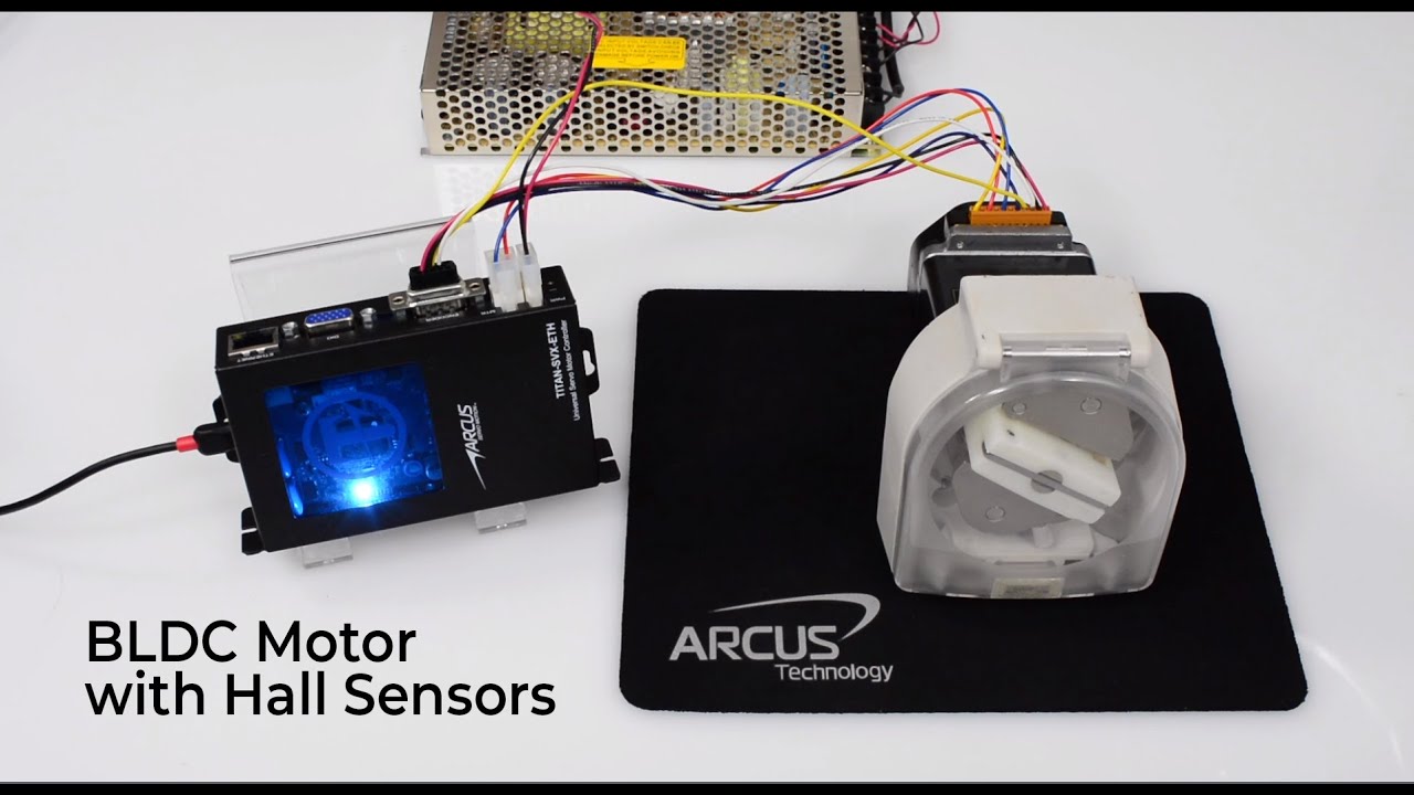
In this tutorial video, we use a 3-phase rotary brushless servo motor with hall sensors to demonstrate the setup process. Watch the video above or continue reading to learn how to set up a BLDC motor with hall sensors.
First, connect the motor to the controller. Power on the controller and open the TITAN software. You should see the TITAN home screen:

Click on the "Communication" window on the top left and press "Check Communication". After you confirm communication, go to the motor setup window to open the motor database wizard. Check the consent window to proceed.
Input the motor details and select your motor type. Rotate the motor shaft and check the hall sensor inputs.
Since we are using hall sensor inputs, check "Hall Only".
Now we're ready to run the auto-detect routine. The software will detect the hall sensor arrangement, check the encoder, and detect resolution to be 0 since we are not using an encoder.
Next the motor, electrical parameters are determined.
Lastly, the motor mechanical parameters are determined. Save these parameters to the database file so you can reuse the database when using the same motor with other TITAN controllers.
Once your save your parameters, you can go back to the home screen on and test the motion. Go to the test drive window and enable the motor. Once the motor is enabled, you can try different jogging or position moves to test the motion of the motor.
You will notice that when you move the motor at slower speeds, the motion will be jerky since the hall sensor resolution is low. Typical applications for such motors should be high-speed velocity control systems such as conveyors or spindle control.
For smoother speed control, consider using the voltage velocity control, which uses open-loop sinusoidal voltage output for smoother motion.
Once you confirm that the motor control is working, the motor may be connected to a gearbox or a load. You will need new mechanical parameters, so go to the tuning section and get the new mechanical inertia and friction values. Check out our documentation on auto-tuning for more information.
As always, please contact our support team for more information. Thank you, and happy servoing!